
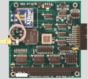
MSI-P710
ZigBee Wireless Card
with Analog In and Digital I/O

The MSI-P710
is a low cost, high performance wireless card providing the ZigBee
protocol using a XBee ZB or XBee-PRO ZB modules operating at an rf
frequency of 2.4
GHz. With advanced mesh networking functionality, XBee and XBee-PRO ZB
modules improve data traffic management and allow for greater node
density. The card is configurable for Transparent or API operation.
Uses simple AT commands with a standard COM port provided by an onboard
UART. The card can function as a Coordinator, a Router or an End
Device in the ZigBee mesh topology.
A
16C550 UART interfaces the XBee module to the PC/104 bus. The UART
provides a 16 byte transmit and receive FIFO and baud rates are
programmable from 1200 to 115,200 bits/s. Automatic hardware RTS and
CTS flow control is used to prevent overflow of the local receiver and
remote receiver FIFOs. The card I/O address is jumper selectable for
COM1 thru COM4 with an optional 16-bit offset address. Ten interrupts
are
jumper selectable for ranges contained in IRQ2 thru IRQ15. The ZigBee
I/O provides 4 lines of analog inputs individually selectable for 0-5V,
0-10V or 0-20mA with 10-bit resolution, and 5 TTL selectable as
input or output. A fused 5V@0.5A is provided on the I/O connector
is available for powering analog and digital sensors connected to the
card. All
I/O lines have varistor surge suppressors for transient voltage
(lightning, etc.)
protection.
The
antenna connection to the card is provided by a SMA bulkhead connector.
A 6" cable attaches this connector to the rf module which permits its
removal from the card
bracket for mounting into the user enclosure as an option. A sample
BASIC test program is
supplied that illustrates programming of the card for various XBee PRO
commands. A BASIC interpreter for running this program is available at
no charge.
Operates from -40° to 85° C and requires only +5V.
Data Sheet (Adobe Acrobat Format)
MSI-P710
User
Manual (Adobe Acrobat Format)
XBee/XBee-PRO ZB User Manual
(Adobe Acrobat Format)
Email: staff@microcomputersystems.com
|